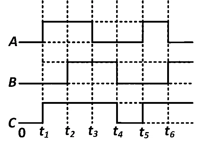
The figure shows a logic circuit with two inputs A and B and the output C. The voltage wave forms across A, B and C are as given. The logic circuit gate is
Solution
Correct option: A
OR gate
Step 1
Read the high and low levels of inputs , , and output from the given waveforms.
Step 2
From the waveform comparison, is high whenever at least one of or is high.
Step 3
Also, becomes low only when both inputs are low: and .
Step 4
This matches the truth table of an OR gate, where .
More Semiconductor Electronics questions to practice
Semiconductor Electronics has 119 previous-year questions in NEET since 2000. It appeared in 100% of the 37 papers analysed. In 2026 it averaged 2.5 questions per paper, about 5.6% of the paper.