Ts Eamcet
Semiconductor Devices And Logic Gates
TG EAPCET 2025 (Online) 3rd May Evening Shift
MCQ+1 / -02025
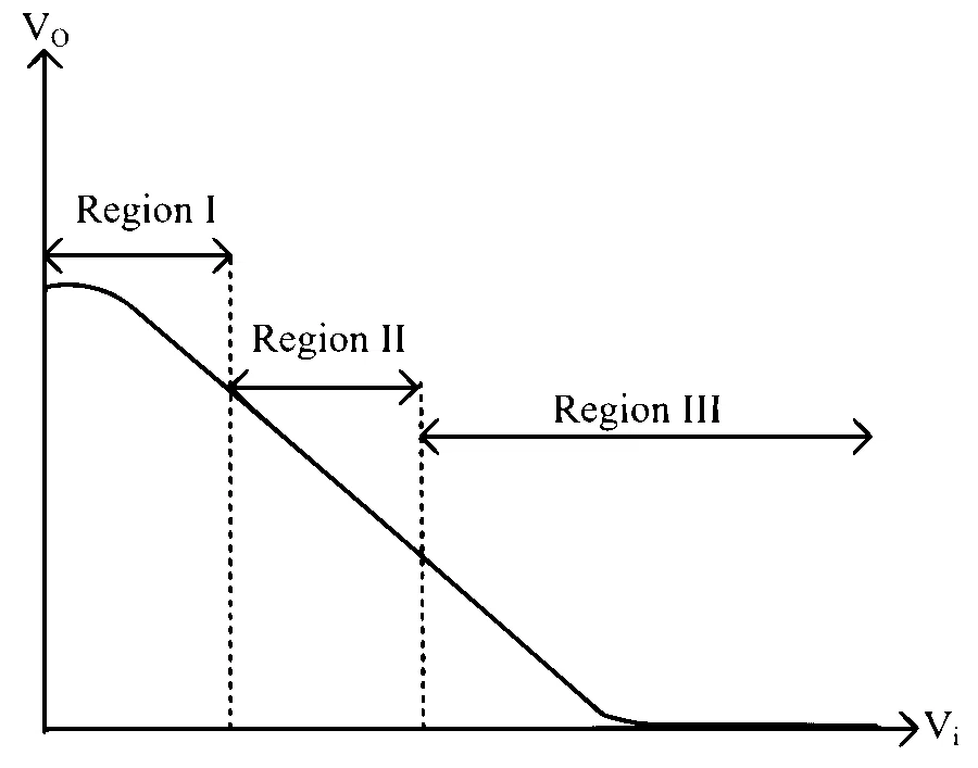
The graph between the input voltage $\left(V_i\right)$ and the output voltage ( $V_o$ ) of a transistor connected in common emitter configuration is shown in the figure. The active, saturation and cutoff regions of the transistor are respectively